
In many of our early conversations with new customers, we emphasize one important principle of metal additive manufacturing: designing a part for traditional machining and designing one for metal 3D printing require different approaches. And by adapting a design for additive, you can lower a part’s cost and simplify the manufacturing process.
The Engineering Process at i3D MFG: How We Review Parts
When we receive a customer’s 3D model, our engineering team first reviews it in SolidWorks for potential printing challenges. If we see features such as sharp right angles or large overhangs, we can often tell that a part was designed around traditional manufacturing methods instead of additive manufacturing.
At that point, we document our notes and recommendations in a design for additive manufacturing (DFAM) report for our customer. If necessary, we also schedule a call to discuss the details. This sometimes becomes an iterative process where the customer takes our suggestions and revises the model before we review it again.
In some cases, customers cannot change the geometry, whether for performance reasons or timeline concerns. We’ll typically still be able to print the part as designed, but the process may be less efficient and more expensive than if we’d been able to implement changes.
But if customers accept our recommendations, they’ll usually see reduced costs and faster lead times. And if they authorize us to modify their model ourselves, we can change it even more quickly and provide a STEP file for final approval.
Example: Adapting an Overhang to 3D Printing
As an illustration, consider a part with a horizontal overhang. With traditional machining, this feature might be produced by removing material, potentially with EDM or milling. In metal 3D printing, however, an overhang must typically be supported during the build, and that creates strategic questions for the manufacturer.
Option 1: Preserving the Geometry
If the customer needs to keep that geometry in place, i3D can add breakaway supports beneath the overhang. The right support design depends on the part and its constraints.
One option is to use wedges in the supports, and a chisel can help separate them after printing. This approach preserves the original geometry of the customer’s part, but the supports use more material and add time and labor to post-processing.
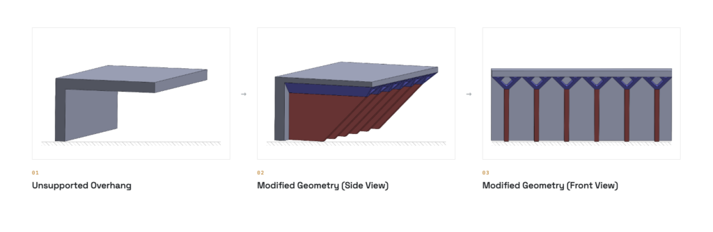
Option 2: Optimizing Geometry to Reduce Costs
If the customer allows i3D to make small changes to geometry, our engineers can consider more efficient ways to make the overhang printable. In the image above, you can see the proposed changes to geometry in blue; the red sections are the support structures that will ultimately be removed.
This approach uses sacrificial “skins,” or thin walls, together with a hollowed-out ceiling wedge. This design requires less support material than an approach that preserves the original geometry.
Our first priority when adding these features is printability. We then look for opportunities to reduce mass and make the remaining supports easier to remove. These goals are directly connected to cost: Reducing the amount of material consumed during the build and increasing the amount of unused powder that can be recovered can reduce material costs.
In addition, easier support removal reduces post-processing labor. And those changes can become especially critical in high-volume production, where per-piece savings add up fast.
Bring DFAM Expertise to Your Project
A truly successful metal 3D printing project requires designing around this specific manufacturing technology. i3D MFG’s in-house engineering team can explain how modifying the original geometry can improve manufacturability and cost, as well as potentially improving performance.
If you are preparing a part for cost-effective production, contact i3D MFG to discuss how DFAM can improve your design.